
















 English
 Français
 Deutsch
 Português
 Español
 русский
  한국어
한국어 العربية
 Italiano
 Indonesia
 Schweiz
 Polski
 Nederlands
 ישראל - עברית
 Perzisch
 ไทย
ไทย 日本語
日本語 ኢትዮ-አማርኛ
 Việt Nam
 Kiswahili
 Srpski
 Ελληνικά
 繁體中文
繁體中文How to Select the Right Fan for an Air Handling Unit (AHU)
08/11/2026A suitable AHU fan therefore needs to be evaluated as part of the whole air system. Airflow, pressure, efficiency, power, controls, noise, physical dimensions, service access, and environmental conditions all influence the final selection.
This article presents a practical selection process that engineers, equipment manufacturers, contractors, and purchasing teams can use when specifying a fan for a new or upgraded air handling unit.
Define the AHU Operating Requirements
The selection process should begin with a clear description of what the air handling unit must accomplish. This includes more than a single design airflow value.
Identify the spaces or processes served by the AHU, the required ventilation strategy, the expected operating schedule, and the different modes in which the system will run. A commercial office AHU may operate at reduced airflow for much of the day, while an industrial unit may need to maintain a more consistent airflow for process reasons. A healthcare or clean environment may have additional requirements related to filtration, pressure relationships, hygiene, or redundancy.
The design team should establish at least the maximum airflow, minimum airflow, normal operating range, supply-air conditions, outdoor-air conditions, and required pressure capability. It should also identify whether the AHU will operate as a constant-air-volume or variable-air-volume system.
If the AHU has several important operating modes, the fan should be checked at each relevant point rather than selected only for the maximum condition.
Calculate the Required Airflow
Required airflow should come from the HVAC design calculations, ventilation requirements, thermal load analysis, process requirements, or another documented engineering basis.
It is generally unwise to increase the airflow value by an arbitrary percentage without identifying why the additional capacity is required. Excessive oversizing can move the normal operating point away from the fan’s preferred range. It may also lead to unnecessary throttling, unstable control, higher sound levels, and avoidable power consumption.
Any allowance included in the airflow requirement should have a defined purpose. For example, the designer may need to consider expected duct leakage, a future expansion that has already been approved, or a specific operating mode with a higher airflow demand.
The required airflow should be expressed in a consistent unit and linked to a defined air condition. This is particularly important when air density may differ substantially from standard rating conditions.
Determine the Total Pressure Requirement
After airflow has been established, the next step is to determine how much pressure the fan must produce.
The pressure requirement includes resistance inside the AHU and resistance in the connected air distribution system. Internal resistance may be created by:
Filters
Heating and cooling coils
Heat recovery devices
Dampers
Humidifiers
Attenuators
Internal transitions
Louvers or screens
External resistance may include supply and return ducts, fittings, fire or smoke dampers, airflow control devices, terminal units, diffusers, grilles, and other downstream or upstream components.
Each pressure value must relate to the same airflow and system condition. Filter resistance deserves particular attention because it changes during operation. The fan should not be selected by combining a clean-filter pressure from one calculation with a loaded-filter condition from another.
The design documentation should state whether the selected pressure represents a clean system, a design loading condition, or another defined operating state.
Understand the Fan Operating Point
A fan does not independently determine the system airflow. The actual operating point is established by the intersection of the fan performance curve and the system resistance curve.
When system resistance increases, the operating point changes. This can happen when filters accumulate dust, dampers move, coils become contaminated, or duct modifications alter the air path. Speed control can compensate for some changes, but it should not be used to conceal an incorrect pressure calculation or a poorly designed installation.
The proposed fan curve should show the required design point as well as important part-load points. Engineers should examine efficiency, input power, fan speed, sound, and motor loading throughout the expected operating range.
The selected point should remain within the manufacturer’s recommended operating area. Operation near unstable regions or outside published limits may cause poor airflow control, excessive noise, vibration, or reduced reliability.
Choose an Appropriate Fan Configuration
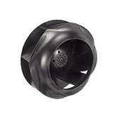
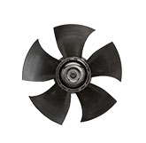
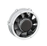
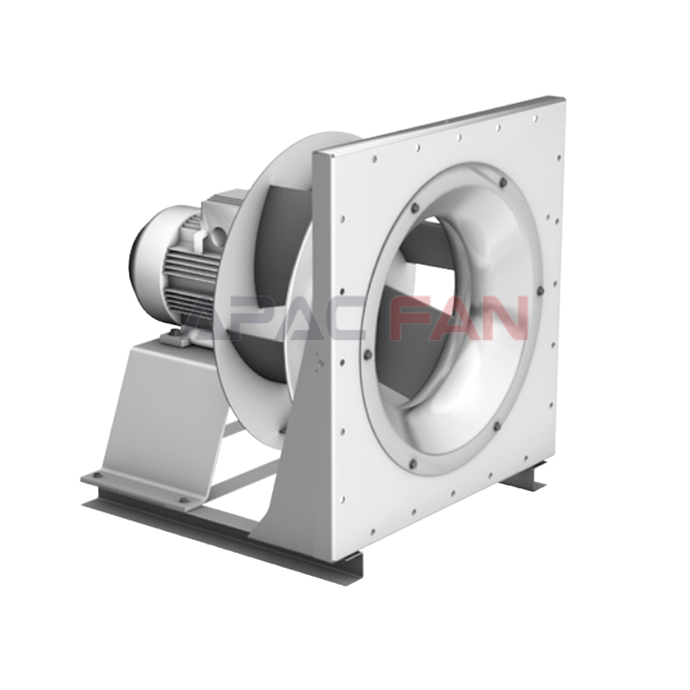
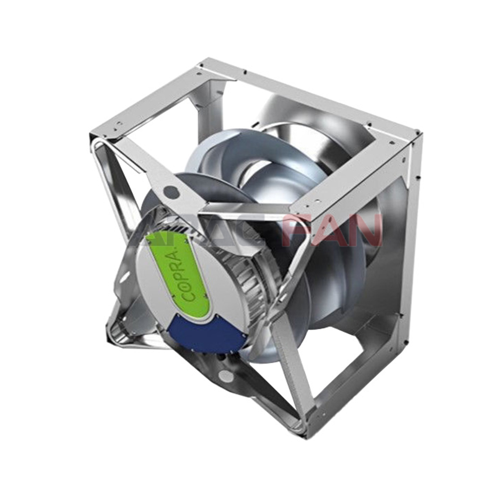
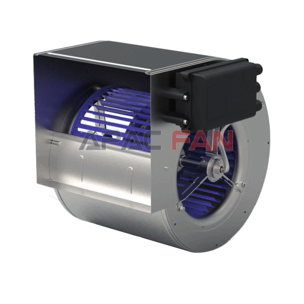
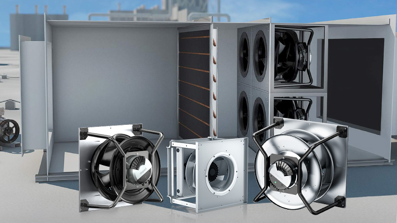
AHUs may use housed centrifugal fans, plug fans, direct-drive fans, belt-driven fans, or multiple-fan arrays. The best arrangement depends on the application, unit size, pressure requirement, available space, control strategy, and maintenance plan.
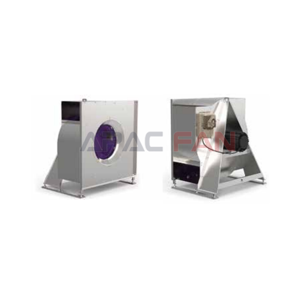
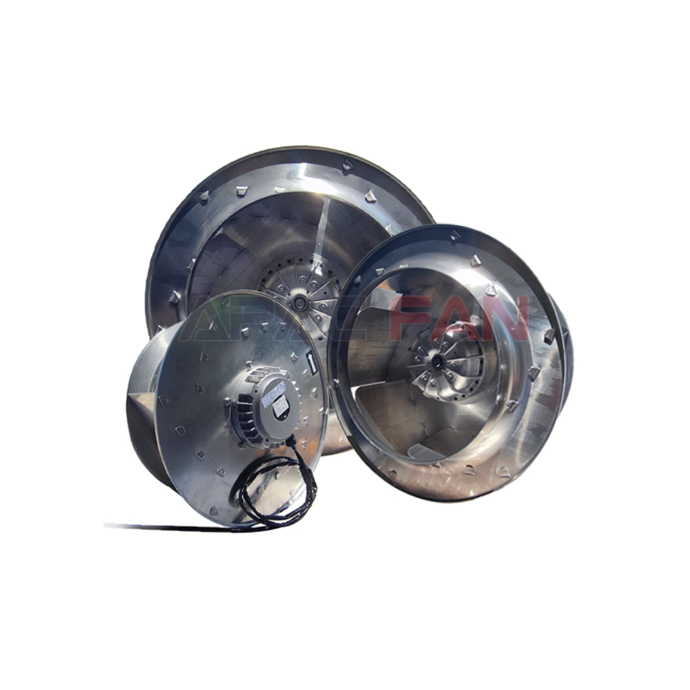
Housed centrifugal fans can provide a defined discharge direction and may suit systems that require connection to a specific outlet. Plug fans discharge into the AHU chamber and can provide a compact arrangement without a conventional scroll housing. Fan arrays use several smaller fans operating in parallel and may offer packaging, control, or redundancy advantages when properly designed.
The fan type should not be chosen from a general preference alone. Its actual performance, arrangement, clearances, access requirements, and interaction with the AHU casing must be evaluated.
For multiple-fan arrangements, confirm how airflow is shared, how inactive fans are isolated if necessary, and how the controls respond when one fan becomes unavailable.
Evaluate EC and AC Motor Options
Both EC and AC motor-based solutions can be used in AHU applications. The correct choice depends on the complete fan package and the project requirements.
EC fans commonly combine an electronically commutated motor with integrated control electronics. They can provide variable-speed operation without a separate external variable frequency drive in many applications. However, the control interface, electrical protection, electromagnetic compatibility, alarm functions, communication options, replacement strategy, and environmental limits still require review.
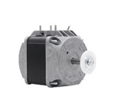
An AC motor may be paired with a variable frequency drive when adjustable speed is required. The motor and drive must be compatible, and the installation should follow the manufacturers’ instructions regarding cabling, grounding, switching, cooling, and permitted speed range.
A meaningful comparison should examine fan efficiency, motor efficiency, drive losses, operating profile, control functionality, service approach, and total installed arrangement. The motor label alone does not determine the performance of the complete system.
Consider Part-Load Efficiency
Many AHUs operate below maximum airflow for significant periods. The selection should therefore consider performance across the anticipated load profile.
A fan that performs well at the design point may not provide the best overall result if it operates poorly at common reduced-flow conditions. Review the fan curve at minimum, normal, and maximum operating points. Check efficiency, speed, power, sound, motor temperature limits, and control stability.
In a variable-air-volume system, the control sequence may reset the static-pressure setpoint based on terminal demand. This can reduce unnecessary pressure generation, but the strategy must be coordinated with the entire air distribution system.
Part-load performance should be evaluated using project-specific operating assumptions. A universal energy-saving percentage should not be applied without a defined baseline, duty profile, system resistance, and control method.
Check Installation Conditions
Catalogue performance is normally based on defined test arrangements. Installed performance can differ if the fan receives distorted airflow or discharges into an unsuitable space.
Obstructions, abrupt transitions, close elbows, uneven inlet conditions, swirl, recirculation, and inadequate clearance can create additional losses. These installation effects may reduce airflow and increase sound or vibration.
The AHU layout should provide the clearances recommended by the manufacturer. Designers should also review inlet guards, flexible connections, structural supports, access doors, cable routes, drainage, internal partitions, and the removal path for major components.
A fan that fits inside the casing is not automatically serviceable. There must be enough space to inspect, clean, isolate, repair, and replace it safely.
Review Acoustic Performance
AHU fan noise should be evaluated as part of the complete acoustic path. Relevant factors include fan type, speed, operating point, blade-passing characteristics, casing construction, vibration isolation, duct layout, silencers, and the sensitivity of occupied spaces.
A single overall sound value may not provide enough information for an acoustic assessment. When the project requires detailed noise control, review sound data by frequency band and confirm the test method and operating condition.
Avoid solving every noise concern by adding a silencer. A silencer introduces additional resistance and may affect the fan selection. It can also generate noise if airflow through it is unsuitable. Acoustic components should be coordinated with the pressure calculation from the beginning.
Verify Electrical and Control Compatibility
Before approving a fan, confirm the electrical supply, maximum current, input power, starting behavior, protection requirements, disconnecting method, control signal, communication interface, and available feedback.
The controls specification should define:
Start and stop commands
Speed reference
Run status
Fault status
Airflow or pressure control
Minimum and maximum speed
Alarm response
Manual and automatic modes
Restart behavior after power loss
Response to sensor or communication failure
For a fan array, the sequence should also address lead-lag operation, speed sharing, fan failure, isolation, and capacity under reduced availability.
The control strategy should be based on the exact selected equipment. Generic control notes may overlook product-specific limits or required protective functions.
Assess Maintenance and Lifecycle Needs
Maintenance requirements influence the long-term suitability of an AHU fan.
Review access to bearings, belts, motors, impellers, electronics, guards, sensors, and electrical connections. Belt-driven arrangements require space for inspection, tensioning, alignment, and replacement. Direct-drive arrangements eliminate belt maintenance but still require access for cleaning, electrical checks, and component replacement.
The operating environment should also be considered. Moisture, dust, corrosive substances, high temperatures, cleaning chemicals, or continuous operation may affect materials, coatings, motor protection, and maintenance frequency.
Service intervals should follow the manufacturer’s instructions and actual site conditions. They should not be copied from unrelated equipment or created without supporting information.
Request Verifiable Manufacturer Data
The final selection should be supported by manufacturer-issued technical information. Depending on the project, the submittal may need to include:
Fan performance curves
Selected operating points
Efficiency data
Input power
Motor rating
Fan speed
Sound data
Electrical characteristics
Physical dimensions
Weight
Materials
Environmental limits
Control information
Installation clearances
Certification or test information
Maintenance instructions
All competing selections should be compared at the same airflow, pressure, air condition, and system boundary. Otherwise, one option may appear better simply because it was evaluated under a different condition.
If important information is unavailable, request clarification. Do not replace missing technical data with an assumption presented as fact.
Plan Commissioning Before Installation
Commissioning requirements should be included before the fan is purchased. This ensures that the necessary sensors, access points, control functions, and testing provisions are available.
Pre-start checks should confirm cleanliness, rotation, fasteners, guards, electrical protection, damper positions, filter installation, sensor locations, and unobstructed airflow.
Functional testing should verify airflow, relevant pressures, fan speed, electrical input, control response, alarms, and operation across important modes. The recorded results should identify the filter condition, damper position, active equipment, control mode, and measurement locations.
If measured airflow is below the requirement, investigate system resistance, filter condition, dampers, duct leakage, rotation, sensor accuracy, and installation effects before increasing speed.
Final Selection Checklist
The right AHU fan should:
- Meet the required airflow and pressure at defined conditions
- Operate within the manufacturer’s acceptable range
- Provide suitable efficiency across expected loads
- Match the available electrical supply and control system
- Fit the AHU without harmful inlet or discharge restrictions
- Meet project acoustic requirements
- Provide safe inspection and maintenance access
- Suit the operating environment
- Include verifiable technical documentation
- Support practical commissioning and future service
Conclusion
AHU fan selection is a system engineering task rather than a catalogue matching exercise. The required airflow and pressure establish the basic duty, but the final decision also depends on the operating range, fan curve, motor and control arrangement, installation geometry, noise, service access, environmental conditions, and commissioning plan.
A defensible selection uses clearly defined inputs and manufacturer-supported performance data. It checks both design and part-load operation, identifies uncertainty, and avoids unsupported assumptions.
When the fan is selected as part of the complete AHU and air distribution system, it is more likely to deliver stable airflow, reliable control, manageable sound, and practical long-term operation.