












 English
 Français
 Deutsch
 Português
 Español
 русский
  한국어
한국어 العربية
 Italiano
 Indonesia
 Schweiz
 Polski
 Nederlands
 ישראל - עברית
 Perzisch
 ไทย
ไทย 日本語
日本語 ኢትዮ-አማርኛ
 Việt Nam
 Kiswahili
 Srpski
 Ελληνικά
 繁體中文
繁體中文How to Improve AHU Airflow and Static Pressure Performance
08/20/2026Define the Performance Problem
Improvement starts by distinguishing airflow from pressure. Airflow is the volume of air delivered, while static pressure represents the potential needed to overcome resistance. A system can have high pressure and poor airflow if a blockage exists, or adequate airflow with excessive pressure if dampers are throttling. Complaints such as hot rooms, noisy diffusers, or weak exhaust do not identify the cause by themselves. Establish the required airflow for ventilation, thermal load, pressurization, or process duty, then measure what the AHU and critical branches actually deliver. Review operating mode, fan speed, damper positions, filter condition, and sensor accuracy before changing setpoints or equipment.
Build a Pressure Profile
A pressure profile shows where the fan’s pressure is consumed. Measure at appropriate locations across filters, coils, dampers, heat-recovery devices, silencers, AHU sections, and major duct segments. The method and instruments should suit the system, with attention to stable test locations and air density where relevant. Compare clean and loaded conditions and check whether measured drops are plausible for the components. One large unexpected loss may reveal a blocked coil, closed damper, collapsed liner, poorly designed transition, or construction debris. Several moderate losses can also add up. The profile turns a vague request for “more pressure” into a targeted list of resistance sources.
Correct Air-Side Restrictions
Basic maintenance often restores lost performance. Replace filters according to an appropriate differential-pressure or maintenance criterion, clean coils and screens, repair crushed flexible duct, open or replace failed dampers, and remove obstructions. Verify that louvers, bird screens, and weather hoods are sized and maintained for the required flow. Internally, loose insulation or an incorrectly installed access panel can block an opening. Avoid removing necessary filtration or sound treatment as a shortcut, because this transfers the problem to indoor air quality, equipment cleanliness, or acoustics. When a component is inherently undersized, increasing its face area or selecting a lower-resistance alternative may provide a lasting improvement.
Improve Transitions and Duct Geometry
Abrupt expansions, contractions, elbows close to the fan, sharp entries, and poorly proportioned takeoffs create turbulence and extra pressure loss. They can also distort flow into the fan so that actual performance falls below the tested curve. Where space allows, use gradual transitions, suitable turning devices, and enough straight or controlled approach to promote uniform velocity. Correct a duct connection that covers only part of a fan-plenum outlet or forces an immediate severe turn. Splitters and perforated plates can improve distribution in some AHUs, but they add resistance and must remain accessible. Geometry changes should be evaluated as part of the complete flow path.
Optimize Fan Selection and Speed
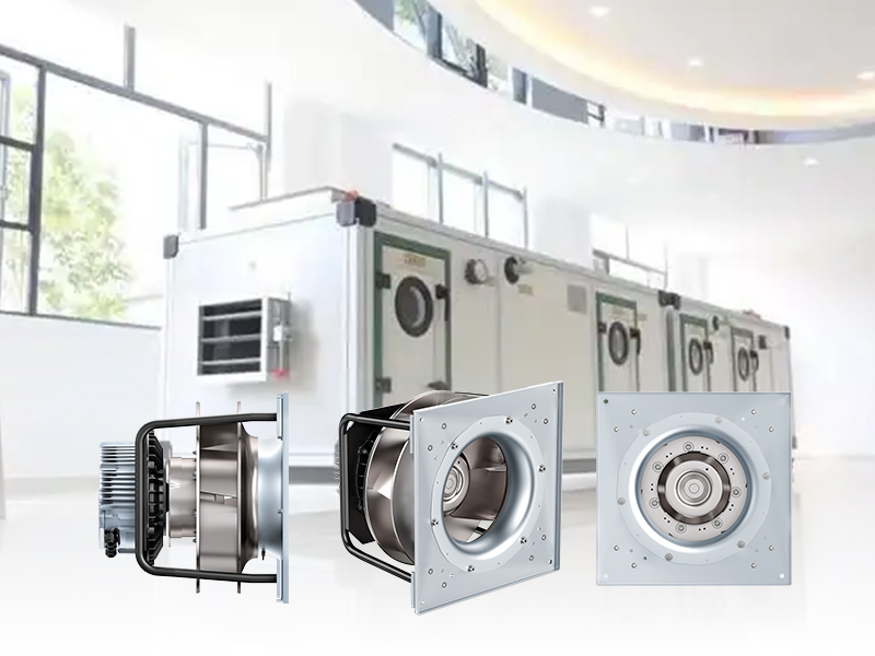
Compare the measured system requirement with the fan curve and operating limits. If the fan is capable but running too slowly, a controlled speed adjustment may solve the problem after mechanical and electrical limits are checked. If it operates near stall, at excessive speed, or far from an efficient region, a different wheel, motor, or fan arrangement may be needed. A larger fan is not automatically better; oversizing can create control and efficiency problems. Confirm rotation, inlet-cone alignment, blade condition, belt ratio where applicable, and actual speed. Any speed increase requires a review of motor power, structural loading, sound, maximum wheel speed, and downstream component limits.
Reset Static Pressure Intelligently
Many variable-air-volume systems maintain more duct pressure than necessary. A static-pressure reset sequence can lower the setpoint when most terminal dampers are partly closed and raise it when critical zones lack authority. The aim is to keep one or a small number of critical dampers near a useful open position without starving ventilation or process loads. Sensor placement matters: a sensor too close to the AHU may not represent remote branches, while one at an unrepresentative endpoint can drive excessive pressure. Reset logic should include limits, delays, fault handling, and stable tuning. Trend analysis is essential to confirm that the sequence reduces pressure without creating complaints.
Balance Supply, Return, and Exhaust
Improving supply airflow alone can disturb building pressure. Return and exhaust systems must respond appropriately, and outdoor-air paths must provide the intended ventilation. Measure airflow relationships rather than relying only on damper position or fan command. Excess positive pressure can make doors difficult to close and drive conditioned air through the envelope; excessive negative pressure can draw in untreated outdoor air and contaminants. In laboratories, healthcare spaces, and industrial buildings, room-to-room pressure relationships may be safety critical. Balancing should therefore proceed from required pressure zones and exhaust needs back to the AHU, with control sequences coordinated across all related fans.
Address Leakage and Bypass
Air that leaks from ducts or bypasses filters and coils may appear in fan airflow measurements without reaching the intended zones or receiving proper treatment. Inspect casing seams, access doors, flexible connectors, duct joints, fire and smoke dampers, filter racks, and coil blank-off panels. Leakage on the suction side can introduce unfiltered air; leakage on the discharge side wastes conditioned airflow. Internal bypass around a coil can create uneven leaving conditions and false confidence in total airflow. Sealing work should use materials compatible with temperature, pressure, fire, hygiene, and maintenance requirements. After repairs, repeat airflow and pressure measurements because the system curve and balance will have changed.
Improve Measurement and Controls
Reliable performance depends on trustworthy feedback. Inspect pressure tubing, sensing ports, airflow stations, transducer ranges, and calibration. A sensor with an unnecessarily broad range may not resolve normal operating changes well, while a clogged port can freeze a false value. Place airflow measurement where the velocity profile supports the device’s requirements or use an approach designed for nonuniform flow. Confirm scaling from sensor to controller and from controller to fan command. Alarms should identify impossible values, command-versus-response failures, and sustained operation at limits. Clear trend displays help operators see whether the problem is demand, restriction, fan capability, or control behavior.
Verify and Sustain the Improvement
After each change, measure airflow, pressure, speed, power, sound, and relevant room conditions under defined operating modes. Confirm that coils, filters, terminals, doors, and pressure-controlled spaces remain within their requirements. Document final setpoints and remove temporary overrides. Seasonal testing may be needed because economizer dampers, filter loading, thermal loads, and occupancy change the system. Establish trends that reveal gradual degradation, such as rising fan speed for the same airflow. Successful airflow improvement is not simply achieving a larger number at the fan. It is delivering the required air to the right locations with stable pressure, acceptable noise, efficient operation, and a maintainable system.